read through the R08h address, the content of the reg-
ister is left unchanged. When read through the CoR
R09h address, the register content will be cleared. A
reset sets R08h/R09h = 00h.
The MAX5935 continuously monitors the power supplies
and sets the appropriate bits in the supply event register
(Table 11). V
DD_OV
/V
EE_OV
is set to 1 whenever
V
DD
/V
EE
exceeds its overvoltage threshold.
V
DD_UV
/V
EE_UV
is set to 1 whenever V
DD
/V
EE
falls below
its undervoltage threshold.
OSC_FAIL is set to 1 whenever the amplitude of the
oscillator signal at the OSC_input falls below a level
that might compromise the AC disconnect detection
function. OSC_FAIL generates an interrupt only if at
least one of the ACD_EN (R13h[7:4]) bit is set high.
A thermal shutdown circuit monitors the temperature of
the die and resets the MAX5935 if the temperature
exceeds +150癈. TSD is set to 1 after the MAX5935
returns to normal operation. TSD is also set to 1 after
every UVLO reset.
When V
DD
and/or |V
EE
| is below its undervoltage-lock-
out (UVLO) threshold, the MAX5935 is in Reset mode
and securely holds all ports off. When V
DD
and |V
EE
|
rise to above their respective UVLO thresholds, the
device comes out of reset as soon as the last supply
Quad Network Power Controller
for Power-Over-LAN
______________________________________________________________________________________ 25
ADDRESS =
08h
09h
SYMBOL
BIT
R/W
R/W
DESCRIPTION
IV 4
7
R
CoR
l
v r rr n fl f r r 4
IVC3
6
R
CoR
Class overcurrent fla for ort 3
IVC2
5
R
CoR
Class overcurrent fla for ort 2
IV 1
4
R
CoR
l
v r rr n fl f r r 1
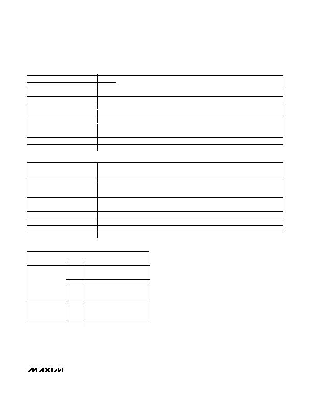
STRT_FLT4
3
R
CoR
Startu failed on ort 4
STRT_FLT3
2
R
CoR
Startu failed on ort 3
STRT_FLT2
1
R
CoR
Startu failed on ort 2
STRT_FLT1
0
R
CoR
Startu failed on ort 1
Table 10. Startup Event Register
ADDRESS =
0Ah
0Bh
SYMBOL
BIT
R/W
R/W
DESCRIPTION
TSD
7
R
CoR
Overtem erature shutdown
V
6
R
CoR
V
v rv l
n i i n
V
DD V
5
R
CoR
V
DD
undervolta e condition
V
4
R
CoR
V
n rv l
-l k
n i i n
V
3
R
CoR
V
v rv l
n i i n
V
EE V
2
R
CoR
V
EE
undervolta e condition
FAIL
1
R
CoR
ill r m li
i
l w limi
V
DD VL
0
R
CoR
V
DD
undervolta e-lockout condition
Table 11. Supply Event Register
ADDRE = h Dh Eh Fh
SYMBOL
BIT
R/W
DESCRIPTION
Reserved
7
R
Reserved
6
R
CLASS_[2]
5
R
CLASS_[1]
CLASS_
4
R
CLASS_[0]
Reserved
3
R
Reserved
2
R
DET_[2]
1
R
DET_[1]
DET_ST_
0
R
DET_[0]
Table 12. Port Status Registers
发布紧急采购,3分钟左右您将得到回复。
相关PDF资料
MAX5937LCESA+
IC HOT-SWAP CTRLR -48V 8-SOIC
MAX5938LEEE+
IC HOT-SWAP CTRLR -48V 16-QSOP
MAX5939EESA+
IC HOT-SWAP CTRLR -48V 8-SOIC
MAX5946LETX+T
IC CNTRLR PCI EXP DL 36TQFN
MAX5948BESA+T
IC CNTRLR HOT SWAP 8-SOIC
MAX5949BESA+T
IC CNTRLR HOT SWAP 8-SOIC
MAX5950ETJ+
IC PWM CTRL HOT-SW 12V 32TQFN-EP
MAX5952CUAX+
IC PSE CNTRLR FOR POE 36-SSOP
相关代理商/技术参数
MAX5935EAX+T
功能描述:热插拔功率分布 Quad Network Power Controller RoHS:否 制造商:Texas Instruments 产品:Controllers & Switches 电流限制: 电源电压-最大:7 V 电源电压-最小:- 0.3 V 工作温度范围: 功率耗散: 安装风格:SMD/SMT 封装 / 箱体:MSOP-8 封装:Tube
MAX5935EAX-T
功能描述:热插拔功率分布 RoHS:否 制造商:Texas Instruments 产品:Controllers & Switches 电流限制: 电源电压-最大:7 V 电源电压-最小:- 0.3 V 工作温度范围: 功率耗散: 安装风格:SMD/SMT 封装 / 箱体:MSOP-8 封装:Tube
MAX5936AAESA
功能描述:热插拔功率分布 RoHS:否 制造商:Texas Instruments 产品:Controllers & Switches 电流限制: 电源电压-最大:7 V 电源电压-最小:- 0.3 V 工作温度范围: 功率耗散: 安装风格:SMD/SMT 封装 / 箱体:MSOP-8 封装:Tube
MAX5936AAESA+
功能描述:热插拔功率分布 48V- Hot-Swap Controller RoHS:否 制造商:Texas Instruments 产品:Controllers & Switches 电流限制: 电源电压-最大:7 V 电源电压-最小:- 0.3 V 工作温度范围: 功率耗散: 安装风格:SMD/SMT 封装 / 箱体:MSOP-8 封装:Tube
MAX5936AAESA+T
功能描述:热插拔功率分布 48V- Hot-Swap Controller RoHS:否 制造商:Texas Instruments 产品:Controllers & Switches 电流限制: 电源电压-最大:7 V 电源电压-最小:- 0.3 V 工作温度范围: 功率耗散: 安装风格:SMD/SMT 封装 / 箱体:MSOP-8 封装:Tube
MAX5936AAESA-T
功能描述:热插拔功率分布 RoHS:否 制造商:Texas Instruments 产品:Controllers & Switches 电流限制: 电源电压-最大:7 V 电源电压-最小:- 0.3 V 工作温度范围: 功率耗散: 安装风格:SMD/SMT 封装 / 箱体:MSOP-8 封装:Tube
MAX5936ABESA
功能描述:热插拔功率分布 RoHS:否 制造商:Texas Instruments 产品:Controllers & Switches 电流限制: 电源电压-最大:7 V 电源电压-最小:- 0.3 V 工作温度范围: 功率耗散: 安装风格:SMD/SMT 封装 / 箱体:MSOP-8 封装:Tube
MAX5936ABESA+
功能描述:热插拔功率分布 48V- Hot-Swap Controller RoHS:否 制造商:Texas Instruments 产品:Controllers & Switches 电流限制: 电源电压-最大:7 V 电源电压-最小:- 0.3 V 工作温度范围: 功率耗散: 安装风格:SMD/SMT 封装 / 箱体:MSOP-8 封装:Tube
